Series 5 Ignition Control Instruction Manual
APPLICATION
The Model Series 5 Direct Spark / Intermittent Pilot Ignition Control Modules are designed for a variety of OEM applications as well as Universal replacements for a wide range of spark ignition controls. Using automatic voltage/frequency sensing, the controls provide operation for spark ignition systems requiring 24Vac or 120Vac, 50/60Hz, with flame rectification flame sensing. The Model Series 5 controls are microprocessor based and provide reliable software control of all timings, sparking control, gas valve operation, flame sensing, and failure recognition with safety shutoff/lockout operation and a corresponding diagnostic LED.
SPECIFICATIONS
- Input Voltage Power: 24 VAC/120VAC 50/60 Hz (+10%/-15%)
- Input Current Drain 0.2A, does not include valve current
- Relay Load Ratings Pilot Valve: 2A maximum Main Valve: 4A maximum
- Operating Temperature Range -40 to +176 degrees F (-40 to +80 degrees C)
- Humidity Range 5% to 93% relative humidity (non-condensing)
- Pre-Purge Time None to 99 seconds
- Inter-Purge Time None to 99 seconds
- Post-Purge Time (Blower Models Only) None to 99 seconds
- Ignition Trial Time 3 to 250 seconds
- Trials for Ignition 1 to 9 trials or 0 = continuous
- Flame Failure Response Time 1.0 second maximum
- Gas Types Natural, LP, or Manufactured
- Blower Load Rating 6A maximum @ 120VAC
INSTALLATION REVIEW
- Installation should be done by a qualified service technician, qualified heating and air conditioning contractor, or licensed electrician.
- Shut off main gas to appliance until installation is finished.
- Disconnect electrical power before servicing
- Ensure proper earth grounding of appliance and burner.
- Ensure proper connections of power and power ground wires.
- Do not exceed the specified voltages and specification ratings.
- Ensure the control is protected from any contact with water.
- All wiring must conform to local and national electrical codes.
- Ensure all wires are labeled before disconnection to prevent wiring errors.
- Ensure all wiring is routed and secured away from flame.
Under heavy demand applications, undesirable shutdowns or control failure could occur due to frequent cycling, harsh environmental conditions related to excessive heat, moisture, or corrosive chemicals. In order to help prevent such circumstances, review the following possible conditions and take the precautionary steps, if necessary.
Water Contact
If the spark ignition control module gets wet, replace it. Mount the control in an area that avoids the possibility of contact with water or steam at any time.
Frequent Cycling
Typical appliance cycling for this control is around 3 to 4 times per hour during the high demand period. However, applications with greater continuous cycling rates can cause the control to wear out more quickly. It is advised to perform a monthly operation check.
High Humidity
Extremely high ambient humidity can cause the spark ignition control to corrode and fail. For use in a humid atmosphere, adequate air circulation around the control is required to prevent condensation.
Dust or Grease
Dust or grease accumulation can cause failure of control operation. Avoid dust or grease accumulation in terminal connection areas of the control.
Corrosive Chemicals
Failure of the spark ignition control can occur as a result of contact with corrosive chemicals, either directly or through the air. Avoid corrosive chemical contact with the control.
Excessive Heat
Excessively high temperatures can damage the control and cause failure. Assure the maximum ambient temperature at the control does not exceed the maximum temperature rating. If the control will be exposed to high temperatures, use air circulation, insulation, and/or shielding as required to protect the control.
INSTALLATION
Perform Safety Inspection
The appliance and venting system must be subject to a safety check before the spark ignition control is installed. If an unsafe condition is detected, remove all power from the appliance and correct the unsafe condition before proceeding with the installation.
Remove Old Control, If Required
First disconnect all power to the old control module. Disconnect and label all wire connections from the old control module. Remove the old control module from its mounting location.
Mount New Control Module
Mount the control in the same location as the old module, if installed as a replacement, or use the control module as a template to mark the mounting hole pattern. Drill new holes as required and fasten securely with two #6 sheet metal or machine screws. The control must be mounted with the terminals facing down, facing sideways left, or facing sideways right. Do not mount the control with the terminals facing the upward position in order to help prevent exposure to water, moisture, corrosive chemicals, grease, and dust.
Connect Wires
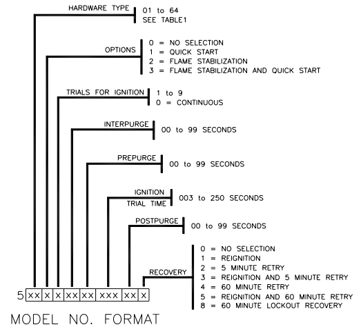
Make sure the thermostat is in the OFF position to assure there is no call for heat. All wiring must conform to local and national electrical codes. Do not allow the spark leadwire to rest against grounded metal surfaces. The burner must be properly grounded in order to accurately sense flame. Determine the control’s hardware type using the Hardware Type Series Guide and attach wire connectors according to the supplied wiring diagram that corresponds to the associated model number.
Cautionary Note
A proper connection must exist between the spark terminal and HV spark gap. However, an open circuit between the spark terminal and spark wire (spark wire not connected) may result in an on board HV discharge for which the circuit is designed to handle without damage.
Hardware Type Series Guide, Table 1
.JPG)
Hardware Type Series Guide, Table 1 (Cont.)
.JPG)
Flame Sense Capability OEM Modes
Hardware Types 37 thru 64: External flame sense
Universal Models
Hardware Types 01 thru 08: Selectable flame sense
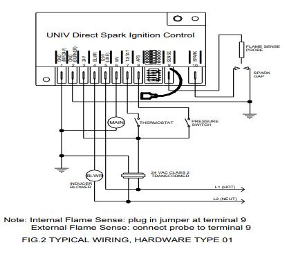
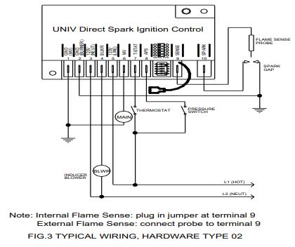
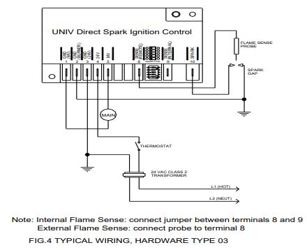
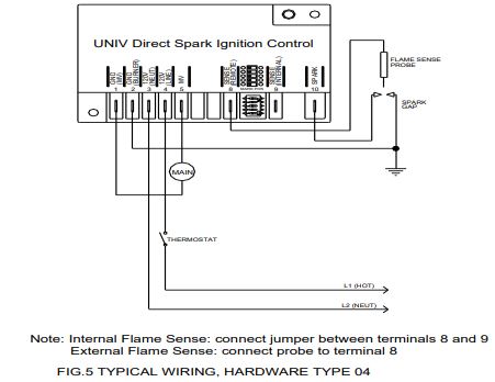
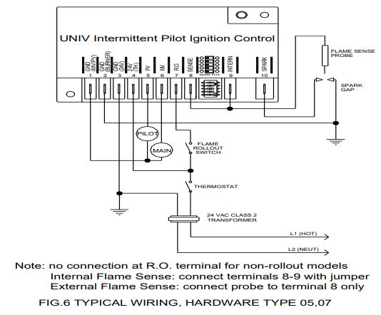
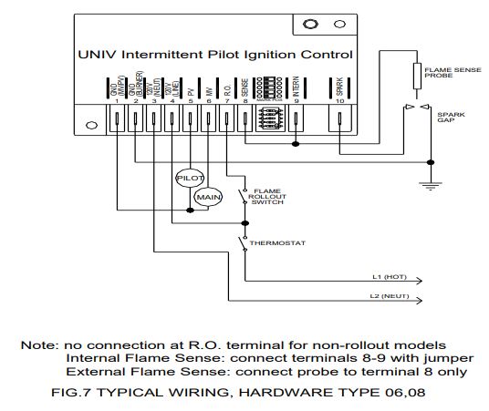
Universal models come with external flame sense active. For internal flame sense, the supplied universal wiring kit jumper must be connected between terminals 8(SENSE)-9(INTERN) for hardware types 05 thru 08, or the jumper plug must be connected to terminal 9(SENSE) for hardware types 01 thru 04. Refer to Hardware Type Series Guide, TABLE 1, page 3. For hardware types 01 thru 04, when using external flame sense, removing the jumper plug by clipping the wire close to the unit is recommended.
Typical Wiring, Hardware Type 01
Typical Wiring, Hardware Type 02
Typical Wiring, Hardware Type 03
Typical Wiring, Hardware Type 04
Typical Wiring, Hardware Type 05, 07
Typical Wiring, Hardware Type 06, 08
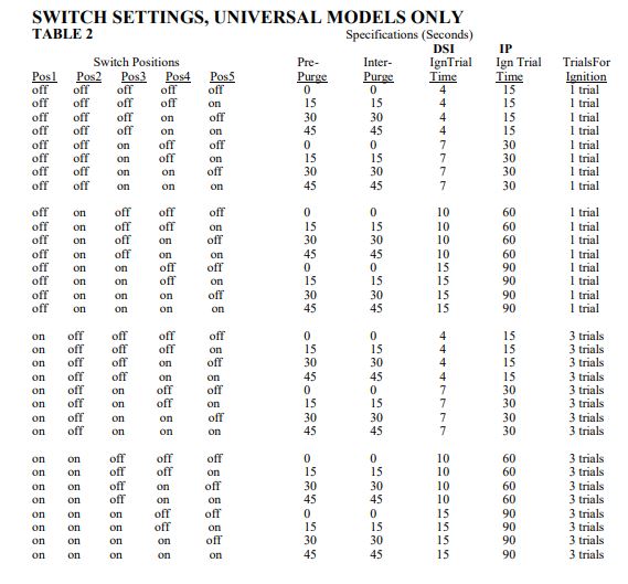
Select Operation Parameter Switch Settings (Universal Models, Hardware Types 01 thru 08 Only)
For universal models only, a 5 position dip switch arrangement is provided to allow field programming for 32 possible pre-defined sets of operation/timing combinations. In order to select/ change settings, assure all power is removed from control module, change switch settings, and then apply power to the control. The dip switches remain active until 10 consecutive power cycles occur without a change in any dip switch setting. Once this occurs, timing specifications are locked, dip switches become inactive, and cannot further be used to change timing specifications. Refer to Switch Settings, Universal Models Only, Table 2.
Sequence of Operation
Normal Operation
Heating cycle starts when a call for heat from thermostat supplies power to the spark ignition control. After a 1 second maximum diagnostic period, the control enters pre-purge mode, or if pre-purge=0, trial for ignition mode begins immediately.
Pre-Purge
The control waits for a time delay equal to pre-purge time. Pilot valve, main valve, blower, and/or alarm relays remain off, and the LED flashes green at a rate of ½ second on, ½ second off. Upon expiration of pre-purge time, the control enters trial for ignition mode.
Trial for Ignition
The control initiates sparking, opens the pilot valve for IP controls or the main valve for DSI controls, and begins the trial for ignition time period. The control will continue sparking for the spark on period, stop sparking for the flame sense period, checking for flame with the flame rectification sensing circuit. If a flame is not detected, the control continues this operation sequence until either a flame is detected or the trial for ignition period terminates. If flame is detected, sparking remains off, the LED stays on solid green, and the main gas valve is opened for IP control models or the main valve remains on for DSI types.
Flame Sensed
With flame present, a current path is completed between the spark electrode and burner ground on internal flame sense models, or between a remote flame rod and burner ground on external flame sense models. The flame is monitored continuously and the pilot and/or main gas valves remain open as long as flame is detected. When the call for heat ends, the thermostat removes power from the control module, thus causing the gas valves to close and the flame to be extinguished.
Flame Not Sensed, Models With 1 Trial for Ignition
If flame is not sensed by the end of ignition trial time, the pilot and/or main gas valve(s) are closed and the control module enters lockout mode. Refer to Error Codes, TABLE 3, page 13. Remove and restore power to end lockout mode. Refer to Troubleshooting Guide, TABLE 4 and Troubleshooting Flowchart, FIG.1.
Flame Not Sensed, Models With Multiple Trials for Ignition
If flame is not sensed by the end of trial for ignition time period, the pilot and/or main gas valve(s) are closed and the control module initiates an inter-purge time delay, followed by another trial for ignition period. For models with 5 minute retry or 60 minute retry enabled, interpurge time delay is 5 minutes or 60 minutes respectively. If flame is not sensed, this sequence is repeated until the total number of trials for ignition are completed. If flame is still not sensed, the pilot and/or main gas valve(s) are closed and the control module enters lockout mode. Refer to Error Codes, TABLE . Remove and restore power to end lockout mode. Refer to Troubleshooting Guide, TABLE 4 and Troubleshooting Flowchart, FIG.1.
Flame Lost
After a flame is established, if a loss of flame occurs during normal burner operation, the pilot and/or main gas valve(s) are closed and the control module initiates an inter -purge time delay, followed by a trial for ignition period. If flame is not sensed, this sequence is repeated until the total number of trials for ignition are completed during this single call for heat. If flame is still not sensed, the pilot and/or main gas valve(s) are closed and the control module enters lockout mode. Refer to Error Codes, TABLE 3, page 13. Remove and restore power to end lockout mode. Refer to Troubleshooting Guide, TABLE 4 and Troubleshooting Flowchart, FIG.1 and Repetitive Flame Loss Error.
Flame Stabilization Option
For models with flame stabilization option enabled, if flame is lost within 5 seconds of flame establishment, the main valve is closed while the pilot valve remains open, the control initiates sparking, and begins a trial for ignition period immediately. If flame is lost after 5 seconds of flame establishment, both main and pilot valves are closed, and the control initiates the inter -purge time delay before beginning another trial for ignition period.
Reignition Option
For models with reignition option selected, if flame is lost anytime after flame establishment, the main valve is closed while the pilot valve remains open, the control initiates sparking and begins a trial for ignition period within 1 second.
Spark On/Off Period
Spark on and off time periods vary, depending on the flame sense type or ignition trial time, as shown by the following information.
Quick Start Enabled
| Flame Sense | Spark On | Spark Off |
| External Sense | 0.3 sec | 0.2 sec |
| Internal Sense | 0.3 sec | 0.7 sec |
Quick Start Not Enabled
| Ign Trial Time | Spark On | Spark Off |
| 3 sec |
2 sec |
1 sec |
| 4 sec | 3 sec | 1 sec |
| 5 sec | 1.5 sec | 1 sec |
| 6 sec | 2 sec | 1 sec |
| 7 sec | 2.5 sec | 1 sec |
| 8 sec | 3 sec | 1 sec |
| 9 sec | 2 sec | 1 sec |
For ignition trial times of 10 to 250 seconds, all spark on/off periods are 2 seconds on and 1 second off except for the final on/off period as shown
| Ign Trial Time | Final | Final |
| Remaining | Spark On | Spark Off |
| 3 sec | 2 sec | 1 sec |
| 4 sec | 3 sec | 1 sec |
| 5 sec | 4 sec | 1 sec |
During most trials for ignition, a flame will be sensed before the final spark on/ off period, such that the final spark on/off period will not be observed.
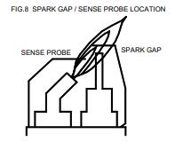
Flame Position
Refer to spark gap / sense probe location, FIG.8, for required optimal flame contact. Flame should be mostly blue in color. Yellow flame indicates burner adjustment is recommended.
Rollout Option
For models with rollout option selected, a rollout switch is wired between the R.O. terminal and 24V(TH) for 24V models or 120V(LINE) for 120V models. The control continuously monitors the rollout switch to be closed. If the rollout switch is detected as open, usually caused by excessive heat due to undesirable flame rollout, the pilot and/or main gas valve(s) are closed and the control module enters lockout mode. Refer to the error codes. Remove and restore power to end lockout mode.
Inducer Blower Operation (DSI Models Only)
For models with blower operation selected, separate thermostat and power inputs are required. Also, a pressure switch input and 120VAC blower output are provided.
Pressure Switch, Initial State
Upon a thermostat call for heat, the control checks the pressure switch (APS) input to verify it is open. If the APS is initially closed, the control waits for up to 30 seconds for the APS to open. If not verified open within 30 seconds from call for heat, the control enters lockout mode. Refer to the Error Codes.
Pressure Switch, Blower On
If the APS is verified open, the combustion blower is energized and the control checks the APS input to verify it closes. If the APS does not close within 30 seconds, the control module enters lockout mode. Refer to the Error Codes.
Normal Operation
If the APS is verified closed after the blower is energized, the control delays for pre -purge time and then enters trial for ignition operation. The thermostat call for heat and main burner flame are continuously monitored. Also, combustion air flow is continuously monitored by reading the APS input to confirm proper air flow.
Pressure Switch, Signal Lost
If the APS is detected as open while flame is present, the control closes the main gas valve and the blower remains on. If the thermostat call for heat remains and the APS closes within 30 seconds of being lost, the control delays pre -purge time and then enters trial for ignition operation. If the APS remains open after 30 seconds, the blower remains on until a power -off reset occurs, and the control module enters lockout mode. Refer to the Error Codes.
Call For Heat Termination
When the thermostat call for heat ends, the gas valve is closed immediately, thus extinguishing the flame, and the blower remains on for the post -purge time.
Post -Purge Termination
When post -purge delay is complete, the combustion blower is de -energized and the control continuously monitors the thermostat input for a call for heat.
Alarm Operation (DSI Models Only)
For models with alarm operation enabled, the alarm output signal is switched on in the event of any condition causing lockout mode operation. Depending on the model selected, the alarm output can be 5VDC, 24VAC, 120VAC, 24VDC(halfwave), or 120VDC(half-wave). The alarm signal is only switched off with a thermostat/power off reset of the control module.
Lockout Recovery (Selectable Option)
The method for recovering from lockout mode is a selectable option defined within the model number.
Thermostat/Power Off Reset
Lockout recovery requires a thermostat reset below ambient temperature and/or a direct removal of power from the control (24VAC or 120VAC depending on the model), followed by a thermostat setting above ambient temperature and/or a reapplication of power to the control. The control will start a new ignition sequence.
Automatic Reset
Automatic reset is enabled if “60 Minute Lockout Recovery” is selected within the model number, shown on page 15. One hour following the lockout, if the thermostat is still calling for heat, the control will automatically start a new ignition sequence in order to light the burner again.
Flame Sense Stuck On
If a flame is sensed at the time the thermostat calls for heat, pre-purge is delayed while the control module continues monitoring flame. If the flame signal disappears within 30 seconds, pre-purge timing begins and normal operation resumes. If the flame signal remains after 30 seconds, the control module enters lockout mode. Refer to error codes.
Repetitive Flame Loss Error
After a flame is established, if a loss of flame occurs 10 consecutive times after flame establishment, the control module enters lockout mode.
Model Series 5 Ignition Control Cross Reference Replaces most models:
Fenwal Series:
- 35 -53
- 35 -60
- 35 -61
- 35 -63
- 35 -70
- 35 -72
Honeywell Series:
- S8600
- S8610
- S8660
- S8670
- S8701
- S87A
- S87D
ICM Series:
- 200
Johnson Control Series:
- G779
- G77x
- S76x
White Rodgers Series:
- 50D
Led Indications, Normal Operation
Green, ½ sec on, ½ sec off- Pre-purge, Inter-purge, Post-purge
Green, blinking rapidly- Trial for ignition
Green, on solid- Flame detected, pilot/main burners on
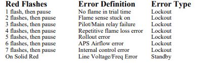
Led Indications, Error Operation
Upon detection of a fault by the control module’s internal diagnostics, sparking is turned off and pilot and/or main gas valve(s) are closed. If alarm option is selected, the alarm output is turned on. The control module then enters lockout mode or standby mode, depending on the error, and flashes a red LED error code. In lockout mode, all operation is disabled. Power removal and/or cycling thermostat to remove the call for heat, thus removing power from the control module, is required to clear the error. In standby mode, the control disables operation until the error is corrected, at which time the normal operation sequence is initiated again. Refer to error codes.
Error Codes
Troubleshooting Guide
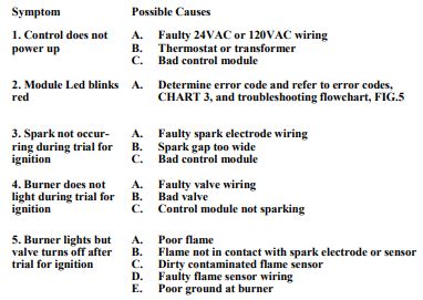
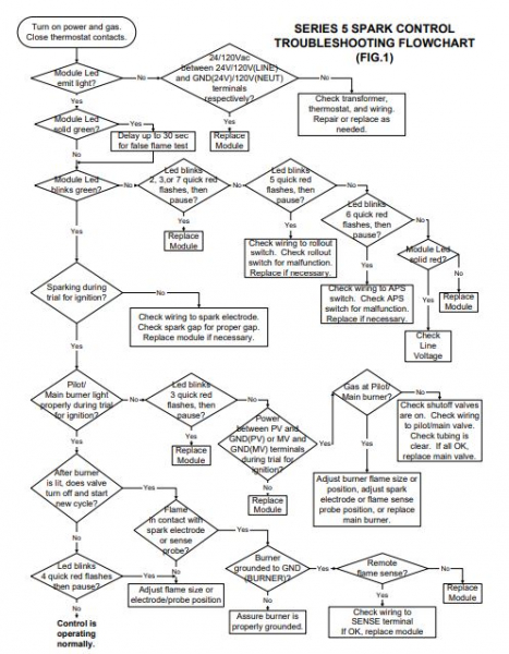
Series 5 Spark Control Troubleshooting Flowchart
MODEL SELECTION
UNIVERSAL MODELS
Universal models come with remote flame sense active. For internal flame sense, the supplied universal wiring kit must be connected between terminals 8-9 for models 05 thru 08, or the jumper plug must be connected to terminal 9 for models 01 thru 04. Selectable operation/timing combinations are shown in Switch Settings, Universal Models Only.
OEM MODELS
A complete range of fixed operation/timing specifications are factory programmable in order to provide complete cross referencing capability for OEM models.